MENU
Skip menuWelcome to FIMP
Introduction
This project will solve many problems. Along with solving problems it will also be very innovative. It will help gamers with better precision, and interact with games. With the haptic feedback feature it will create a real life experience for the user and allow them to make better decisions. Scientists and engineers can use this arm, for experiments where they need to have certain amount of distance clearance from the test site. It can also withstand great amounts of temperature that the normal human hand or body wont be able to bear. Scientists can deal with hot object like lava rocks, or other hot surfaces. These arms can also be used in space, where the astronauts can use the arm from their space ship. With the help of the app, and the integrated camera it will allow users to interact with the environments outside of their reach, and capabilities. Also the app will be saving information received from the arm, and provide logs, so the user can use it to make his/her reports and also use the information to make changes to better the app or hardware.
Budget
The budget was planned to be under 200$ Canadian dollars, unfortunately I surpassed that limit and had to get a new Raspberry Pi and few other items so my budget has increased slightly.
- New Raspberry Pi 3 kit - $99 CAD
- Raspberry Pi camera module - $25CAD
- Robot arm Kit - $70CAD
- Flex Sensor (4.5") - $18.49 CAD X 4
- Adafruit 16-Channel PWM $34
- Buying All the Parts - 1-2 Weeks
- Building Robot - 4hours
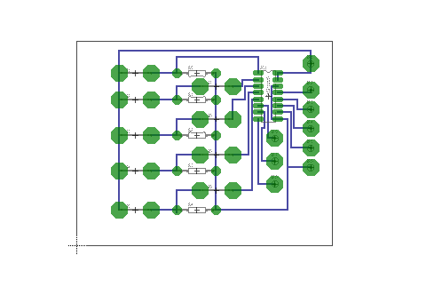
- Building PCB - 3hours
- Programming - 1 week
- STEP 1
- STEP 2
- STEP 3
Time Commitment
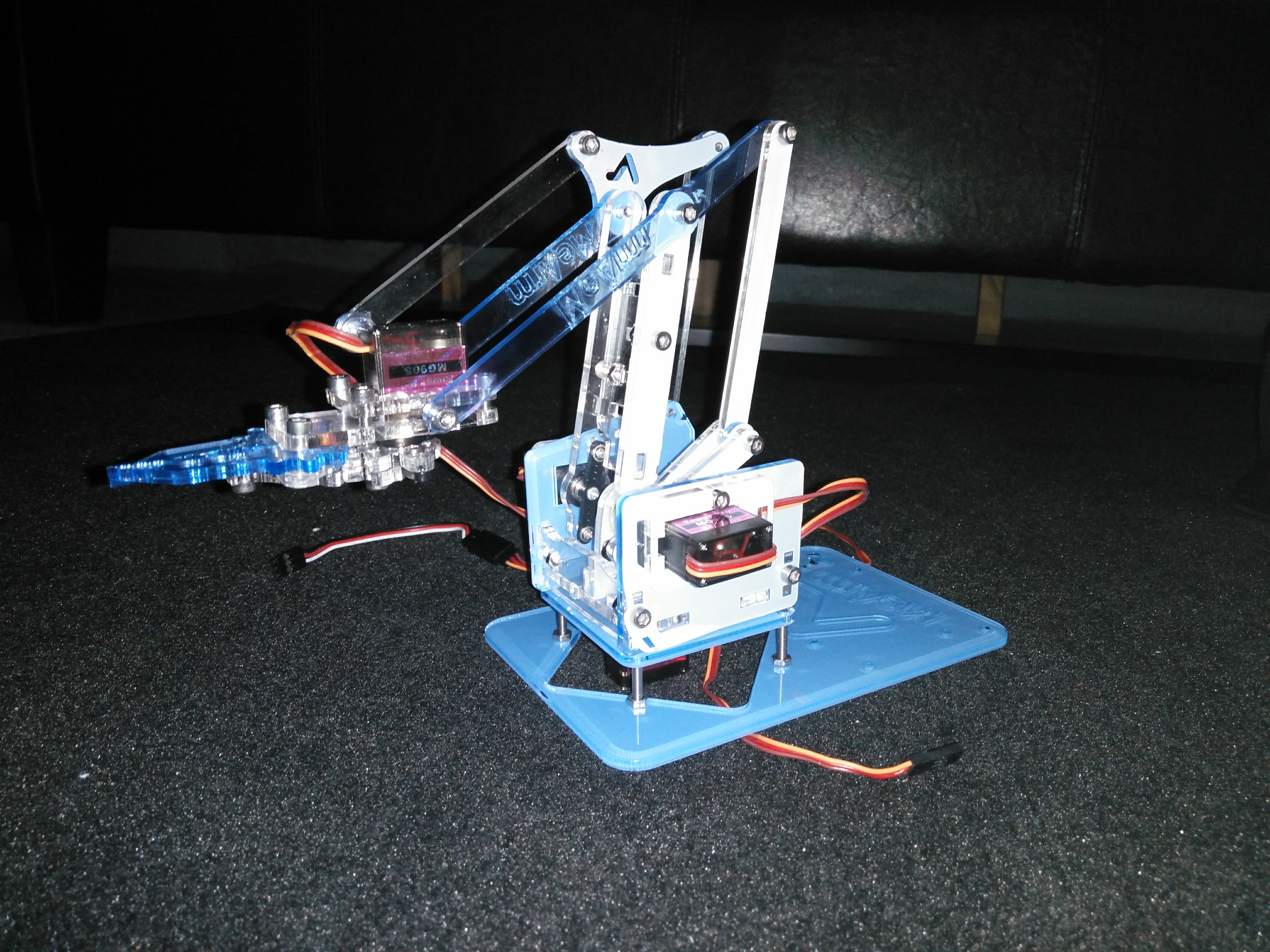
Mechanical Assembly
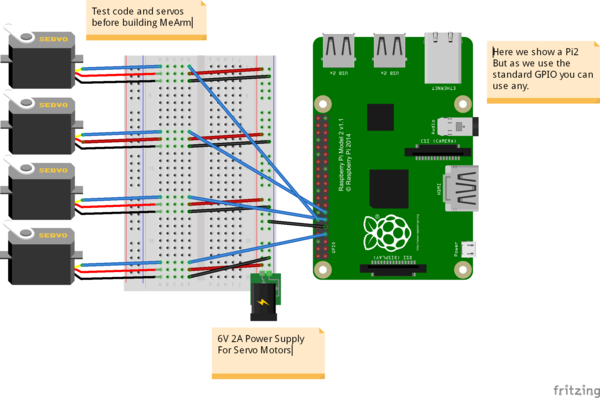
The MeArm should be fun to build and easy to control. We’ve spent a lot of time putting together instructions for building and controlling the MeArm. We advise that you work out and test how to control your Servo Motors before constructing your MeArm. It will save you time and frustration, and lessen the chance that your MeArm will just be something cool to sit on your shelf.
Click on link and follow the steps
Using A Flex sensor and Servo On The Raspberry Pi Using An MCP3008
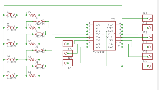
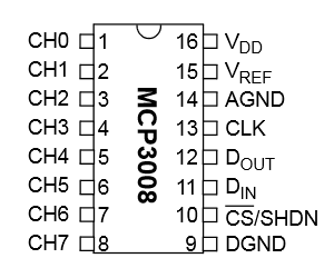
MCP3008
In order to measure the X and Y voltages I decided to use an MCP3008 10 bit Analogue to Digital Converter.
These devices are cheap, easy to setup and allow 8 analogue inputs to be read by the Pi using it’s SPI interface.
In this tutorial we will only need three of its inputs.
VDD   3.3V
VREF  3.3V
AGND  GROUND
CLK   GPIO11 (P1-23)
DOUT  GPIO9  (P1-21)
DIN   GPIO10 (P1-19)
CS    GPIO8  (P1-24)
DGND  GROUND
Breadboard Circuit
Here is my test circuit
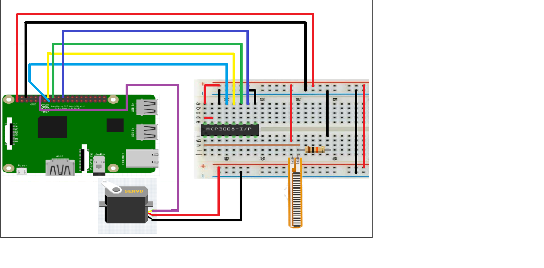
The MCP3008 is wired up just as it was in my previous post :
MCP3008           Pi
			--------------    ----------------
Pin 1  (CH0)      -
Pin 2  (CH1)      -
Pin 3  (CH2)      -
Pin 9  (DGND)     Pin 6  (Ground)
Pin 10 (CS)       Pin 24 (GPIO8)
Pin 11 (DIN)      Pin 19 (GPIO10)
Pin 12 (DOUT)     Pin 21 (GPIO9)
Pin 13 (CLK)      Pin 23 (GPIO11)
Pin 14 (AGND)     Pin 6  (Ground)
Pin 15 (VREF)     Pin 1  (3.3V)
Pin 16 (VDD)      Pin 1  (3.3V)
Python Test Script
#!/usr/bin/env python
import time import RPi.GPIO as GPIO GPIO.setmode(GPIO.BCM) GPIO.setwarnings(False) # read SPI data from MCP3008 chip, 8 possible adc's (0 thru 7) def readadc(adcnum, clockpin, mosipin, misopin, cspin): if ((adcnum > 7) or (adcnum < 0)): return -1 GPIO.output(cspin, True) GPIO.output(clockpin, False) # start clock low GPIO.output(cspin, False) # bring CS low commandout = adcnum commandout |= 0x18 # start bit + single-ended bit commandout <<= 3 # we only need to send 5 bits here for i in range(5): if (commandout & 0x80): GPIO.output(mosipin, True) else: GPIO.output(mosipin, False) commandout <<= 1 GPIO.output(clockpin, True) GPIO.output(clockpin, False) adcout = 0 # read in one empty bit, one null bit and 10 ADC bits for i in range(12): GPIO.output(clockpin, True) GPIO.output(clockpin, False) adcout <<= 1 if (GPIO.input(misopin)): adcout |= 0x1 GPIO.output(cspin, True) adcout >>= 1 # first bit is 'null' so drop it return adcout PWMOUT = 18 SPICLK = 22 SPIMISO = 23 SPIMOSI = 24 SPICS = 25 # set up the interface pins GPIO.setup(PWMOUT, GPIO.OUT) GPIO.setup(SPIMOSI, GPIO.OUT) GPIO.setup(SPIMISO, GPIO.IN) GPIO.setup(SPICLK, GPIO.OUT) GPIO.setup(SPICS, GPIO.OUT) # 10k trim pot connected to adc #0 potentiometer_adc =0; pwm_freq = 50 # Set the PWM frequency to 50 Hz last_read = 0 # this keeps track of the last potentiometer value tolerance = 0 # to keep from being jittery we'll only change # volume when the pot has moved more than 5 'counts' # Configure the PWM pin p = GPIO.PWM(PWMOUT, pwm_freq) # channel=18 frequency=50Hz p.start(9) try: while True: # we'll assume that the pot didn't move trim_pot_changed = False # read the analog pin trim_pot = readadc(potentiometer_adc, SPICLK, SPIMOSI, SPIMISO, SPICS) # how much has it changed since the last read? pot_adjust = abs(trim_pot - last_read) if ( pot_adjust > tolerance ): trim_pot_changed = True last_read = trim_pot if ( trim_pot_changed ): pwm_pct = round((trim_pot) / 2) # Determine current voltage percentage pwm_pct = int(pwm_pct) # Cast the value as an integer DC= 1./18*(pwm_pct) print "ADC read: ", trim_pot print "PWM percentage: ", pwm_pct print "PWM Duty Cycle: ", DC p.ChangeDutyCycle(DC) # hang out and do nothing for a half second time.sleep(0.5) except KeyboardInterrupt: pass p.stop() GPIO.cleanup()Making PCB for Flex Sensor